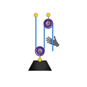
The 2:1 Pulley System
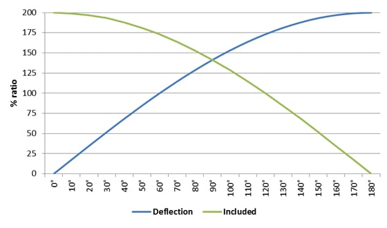
Angular vector forces occur when ropes are passed through a deviation or a directional pulley. Dependent on the angle created, this can have a multiplying…
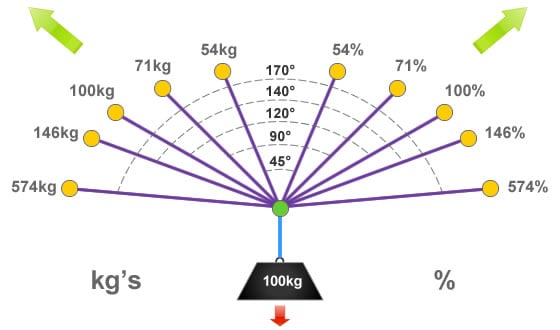
Vector forces become apparent whenever there is an internal angle greater than 0° between two or more rigging components or anchorage points. For ease of…
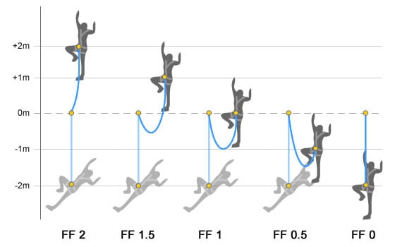
A fall factor is a simple representation of the severity of a fall. It can be used to evaluate the potential loadings exerted on the…
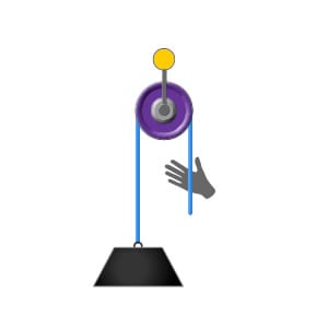
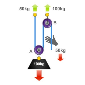
In the illustration to the right we have a rope attached to a load weighing 100kg. The rope has been passed through a pulley which…
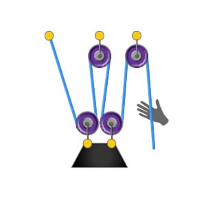
This pulley system provides a 4:1 mechanical advantage. The user is required to apply a force of 25kg to raise this 100kg load, for every…
Please confirm you want to block this member.
You will no longer be able to:
Please note: This action will also remove this member from your connections and send a report to the site admin. Please allow a few minutes for this process to complete.