Angular Vector Forces
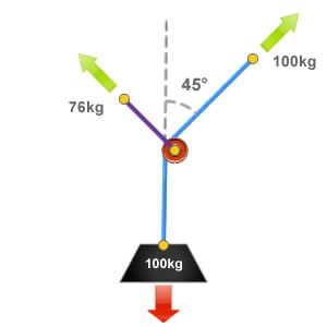
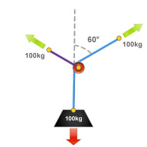
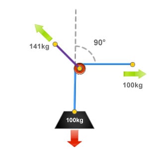
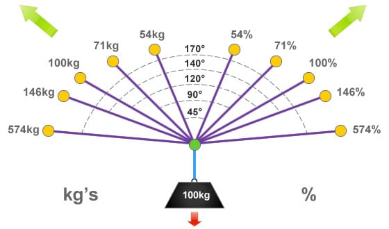
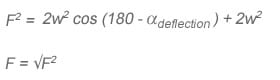
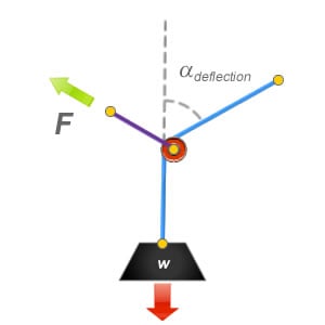
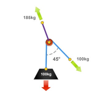
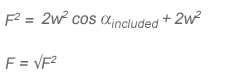
Angular Vector forces can be calculated using mathematical formula. Here is a formula that we can use to calculate the amount of force that is being applied to the deviation or directional pulley anchor point when measuring from the angle of deflection.
So far on this page we have used kilograms to represent the loads in the illustrations. As a kilogram is a measurement of mass, this should be converted to weight (Newtons) to calculate the resultant force correctly.
Where:
F is the resultant force exerted to the deviation or directional pulley anchor point.
w is the weight of the load.
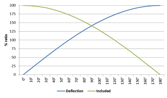
α is the angle that the rope has been deflected away from its original line.
The percentage factor can be used to calculate the amount of force that is being applied to the deviation or directional pulley anchor point. This can be achieved by using the following formula:
![]()
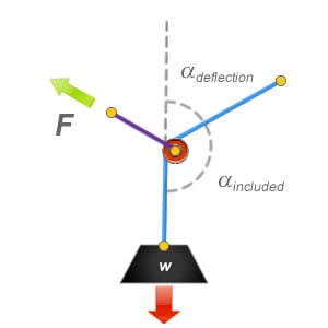
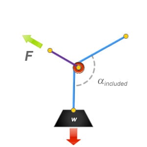
Angular Vector forces can be calculated using mathematical formula. Here is a formula that we can use to calculate the amount of force that is being applied to the deviation or directional pulley anchor point when measuring from the included angle.
So far on this page we have used kilograms to represent the loads in the illustrations. As a kilogram is a measurement of mass, this should be converted to weight (Newtons) to calculate the resultant force correctly.
Where:
F is the resultant force exerted to the deviation or directional pulley anchor point.
w is the weight of the load.
α is the angle that the rope has been deflected away from its original line.
The percentage factor can be used to calculate the amount of force that is being applied to the deviation / directional pulley anchor point. This can be achieved by using the following formula:
![]()