Vector Forces
Vector forces can be calculated using mathematical formula. So far on this page we have used kilograms to represent the loads in the illustrations. As a kilogram is a measurement of mass, this should be converted to weight (Newtons) to calculate the resultant force correctly.
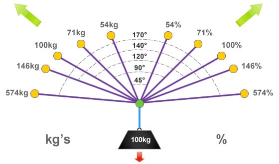
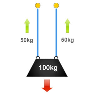
Providing that the rigging components are sharing the weight of the load equally, such as in a ‘Y’ hang then the following equation can be used:
![]()
Where:
F is the resultant force exerted to each anchorage.
w is the weight of the load.
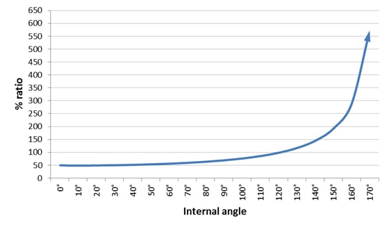
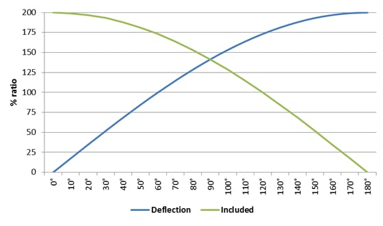
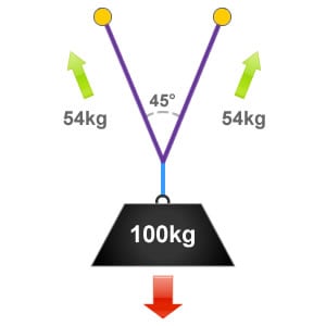
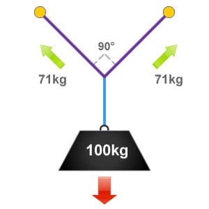
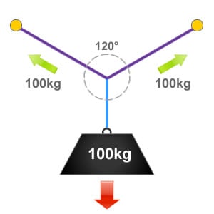
α is the internal angle between the two slings.
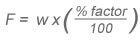
It is not always the case that the load will weigh 100kg, it is far easier to calculate the relevant vector forces from a percentage ratio. This can be achieved by using the formula:
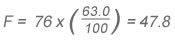
 For example if we had a load weighing 76kg suspended from a Y-hang rigging configuration with an internal angle of 75° then:
| Angle | % factor | Angle | % factor | Angle | % factor |
|---|---|---|---|---|---|
| 0° | 50.0 | 65° | 59.3 | 130° | 118.3 |
| 5° | 50.1 | 70° | 59.3 | 135° | 130.6 |
| 10° | 50.2 | 75° | 63.0 | 140° | 146.2 |
| 15° | 50.4 | 80° | 65.3 | 145° | 166.8 |
| 20° | 50.8 | 85° | 67.8 | 150° | 193.2 |
| 25° | 51.2 | 90° | 70.7 | 155° | 231.0 |
| 30° | 51.8 | 95° | 74.0 | 160° | 287.9 |
| 35° | 52.4 | 100° | 77.8 | 165° | 383.1 |
| 40° | 53.2 | 105° | 82.1 | 170° | 573.7 |
| 45° | 54.1 | 110° | 87.2 | 175° | 1146.9 |
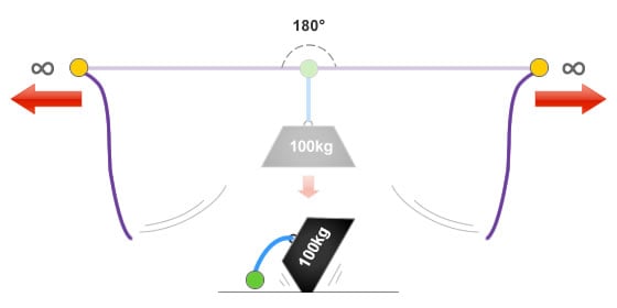
| 50° | 55.2 | 115° | 93.1 | 180° | ∞ |
| 55° | 56.4 | 120° | 100.0 | ||
| 60° | 57.7 | 125° | 108.9 |